Wavefront Planning-Task 4

Task: Path Planning

Group Members:

Flynn Darko

Selase Attah Kwamuar

Lecturer: Dr. Ayorkor Korsah

Task 4 Report

Introduction & Objective

The task required us to implement the wavefront planning algorithm to enable our robot plan its way through a specified map from a start point to a goal area.

Design Concept

The task required us to implement the wavefront algorithm in an enclosed map that was divided into grids and with “x” and “y” coordinates/boundary. The figure below shows the whole map divided into grids. The numbered grids each have an x and y coordinate and contain the numbers 0 and 1 which specify free spaces and obstacles respectively.

Figure 1: Our World Map

Figure 1: Our World Map

As can be seen above figure 1, gives a summary of the task our robot is to perform. The robot is supposed to start at the “start cell” and follow along the red line until it gets to the goal cell or area. In the implementation section of the report, the program is explained further.

The concept we decided to follow is as follows;

  • Get specified map
  • Populate map from goal area
  • Calculate and find shortest path
  • Using the shortest, navigate to the goal area

Implementation in RobotC Language

Before going ahead to write the program to implement the wavefront algorithm the pseudo code that follows explains the structure of the our program;

Cell Population

Set value of goal cell to 2

Enqueue goal cell

         While  (start cell has not been processed)

                currentcell = Enqueue

                Expand currentcell

                for each neighbor of currentcell, set neighbor’s value to currentcell value

                Enqueue neighbor

Path Extraction

Start at the start cell

While not at goal cell

                Move to the neighbor cell with the smallest value which is an not obstacle

Navigate to goal Cell


Implementation Stages

Movement through the map (tiles)

To do this we had to calculate the distance between the center points of two cells

And write a turnLeft() and turnRight() function for our robot.

Writing a function for the movement of the robot was the first part of the task we implemented. After using and observing how the encoders work and using the distance calculated for the tile distances we implemented forward, left, and right movement of our robot. The respective functions used in our program were moveForward(), ninty_turnLeft() and the ninty_turnRight(). We also had to make sure that for the left and right turns our robot turned 90 degress for both turns. We were able to do this by adjusting the magnitude of the power assigned to the both wheels for the respective turns.

Displaying the map on NXT screen

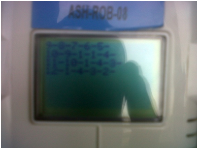
To implement this we used a printWaveMap( ) method to display the map specified in the planning_map.h source code. Using the nxtDisplayString( ) method we printed the various map values in the various cells, specifying the free cells with 0, obstacles as 1 and the goal cell as 2 as can be seen in figure 2.

figure 2

figure 2

Populate the cells from the goal area to start area

After implementing the display of the given map on the screen of the robot, we went ahead to populate the cells within the map starting from the goal cell.  That is, the wavefront plan. We used unique functions namely addQueue( ) and removeQueue( ) to queue all the processed cells until we got to the start area. These functions also made use of variables which were passed as parameters in the function to queue up the values of the neighboring cells as they were populated. From figure 3, it can be seen that from the goal area 2, we populate the neighboring cells which are enqueued till we get to 12 which is the start area.


figure 3

figure 3

Planning and Navigating through planned path to goal

Finally, we made use of the movement function and the wavefront plan to implement finding the shortest path and navigation to the goal area. The program algorithm we wrote for this implementation is as follows;

  1. Given the start cell of robot
  2. Get value of cell
  3. Compare value of that cell to its neighboring cells and find the least cell value
  4. Repeat steps 1,2 and 3 till it gets to the goal cell which is 2
  5. Save shortest path in an Array

After finding the shortest path to the goal we encountered the challenge of factoring in the orientation of the robot. Relative to the bearing of the world map we were using, the orientation for the robot changed after a turn.

We therefore had to use a variable called heading which was assigned variables representing the current bearing of the robot. In our program this enabled us to inform the robot to know the position of the minimum cell to itself and know which direction to turn in order to get to the right neighboring cell with the minimum number.

figure 4

figure 4

Challenges

On major challenge we faced was how to factor in the orientation for the robot. After getting an understanding of the concept of how to use it, we still had a lot of errors when implementing it in our program. We had to write about sixteen conditions for all possible positions of the minimum cells the robot was supposed to move to and the current orientation for the robot as well. We were however finally able to have our program ran by writing a condition for all four possible orientations for the robot. This included a condition for when the robot was facing north, east, south and west. Each condition included the action the robot was to take depending on where the minimum value cell was to the robot.

During our testing, we also realized that our robot did not exactly turn 90 degrees for both left and right turns. We therefore had to adjust the assigned motor powers as well as the wait times.

Conclusion

After debugging our program following each unit task we realized that our approach to the task cost us a lot of time on the whole task. What we had to do first was implement the movements function and make sure our turns worked before writing our program for the wavefront plan. This would have saved us some time since we had to go back and correct the movement functions.

In summary this task was challenging in terms of determining the orientation of the robot upon every turn but it taught us the value of breaking a problem or a solution algorithm down to the very minute detail since this really helps when writing the program.

Final Project. Building a Sorter Robot

Task: Building a Sorter Robot

Flynn Darko

Lecturer: Dr. Ayorkor Korsah


Final Robotics Project


Introduction & Objective

The objective of this project was to build and program a robot that would sort a number of maize grains painted in different colors. When the color of the painted grain is detected, the sorter robot places it in the assigned container placed in front of it. The robot is supposed to do this until all the grains are sorted into the respective containers.


Design Concept

Structure

My first conception of the how the structure of the sorter robot should be was first influenced by a model I saw online which looked like the one shown in figure 1.   I therefore went ahead to build the model using the building instructions that came with it. However, I had stated in my proposal that I was going to make use of colored maize grains. But looking at the model I had decided on, the grains could not be transported along the inclined structure that this model provided. The model could work well for colored balls which would fall along the inclined Lego brick. Though presented as my first milestone, I decided to work a new model which would be more efficient in transporting the grains during the sorting process. Using a conveyor belt was my next design concept.

figure 1: First sorter robot model

figure 1: First sorter robot model

As shown in figure 2, I saw another model which I knew would be the best robot structure model to use. Having no building instructions, I had to build it myself using the various parts from the NXT Mindstorm Lego kit. This took a great deal of the time I had to finish the whole project.


New Picture (1)

figure 2

New Picture (2)

figure 2

Program Algorithm

During the building process of the sorter robot, I had the following algorithm concept in mind which I wanted to implement

  1. Detect and display grain color on NXT screen
  2. Upon detection, stop upper conveyor belt and turn lower conveyor belt (upper conveyor and lower conveyor shown as Uconv and  Lconv in figure 3) to the respective bin collector
  3. Start upper conveyor again till the grain drops in the collector.
  4. Reset lower conveyor to original position
  5. Repeat steps I to IV until all the grains placed on the sorter robot are sorter into their respective bins

The next progress was the implementation stage.

New Picture (3)

figure 3

Implementation

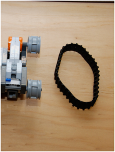
The above figures (figures 2 and 3) show the model of the robot I built. I used a color sensor to help detect the color of the Lego brick color (the colored maize grains were not being detected well by the color sensor so I used Lego bricks instead).  In order to get a conveyor belt I attached a motor to a wheel which had a conveyor belt wrapped around it. This is shown in figure 4.

New Picture (4)

figure 4

Untitled-3

Challenges

As already mentioned, getting the structure of the sorter robot right was the one major challenge I faced. Though I had the program algorithm written down, I could not implement it without building the sorter robot. I was therefore able to implement the program for the sorting process very late to the due date for demonstration. During demonstration, I still had some modifications to make to the rotation of the lower conveyor (Lconv) so that it moved towards the right bin throughout the sorting process.

Conclusion

This final project proved to be very challenging since I had to build the robot from scratch without any building instructions. However, I found it very fulfilling when I was finally able to get it done an implement my program.

Relevance to Problem Solving in Ghana

In Ghana we could have robots that can sort waste to hasten the process of recycling. For example in homes, such robots can be programmed to sort waste materials into labeled bins which would make the reuse of waste possible and much easier.

Treasure Hunt Task

Task: Treasure Hunt

Group Members:

Flynn Darko

Daniel Botchway

Lecturer: Dr. Ayorkor Korsah


Task 3 Report

Introduction & Objective

Our main goal for this task was to write a program for the robot that would enable it find red and blue colored bottles and place them in their respective color zones (holding stations) with the help of sensors attached to the robot.

Design Concept

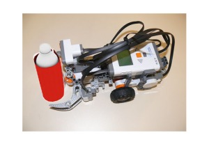
First, we had to rebuild our robot from task 2 to enable it grab and transport the bottles to the collection points. Treasures are shown in figure 1.

Bottles wrapped in colored cards

Bottles wrapped in colored cards (treasures)


  • For the robot and its sensors

For our robot we decided on the “Tribot” model of the robot. The sensors we decided to use were two sonar sensors and two color sensors. For the sonar sensors, one was placed at the top and the other placed by the side of the robot. The concept we wanted to implement with these two sensors was to use the top sonar sensor for front obstacle (wall) detection and the side sensor for side obstacle (wall) detection and avoidance.

Also, one color sensor faced downwards while the other was place in front of the robot. With the front color sensor detecting, finding and recording the color of a bottle and its color the downward color sensor would use that data to find the respective collection zone that has the same color as the bottle detected.

  • For our solution concept, the process goes like;
  1. Do random exploration in the environment to find colored bottles while avoiding obstacles.
  2. On finding bottle, save color of the bottle, grab the bottle and move along the wall of the environment.
  3. When the appropriate color zone is detected, drop bottle.
  4. Continue with the random exploration.

Implementation

Our first step in the implementation stage was building our robot. The robot had to have arms to enable grabbing of the bottles. The arm that was meant to grab the bottles needed a motor to control the opening and closing of the arms. The color sensors were placed in front of the robot in between the arms with one sensor horizontally positioned to detect the color of obstacles in front of the robot. Another color sensor was place vertically, so that it the sensing area pointed down, in order to detect the color of the landing zones.

The next step was programming the robot to use its sonar sensor inputs to do wall-following. This we programmed using the Bang-Bang and P control mechanisms. Though the wall following program worked along a straight wall, it failed in the treasure hunt environment because of the acute angular nature of the boundaries. With that situation, we had to implement a wall avoidance procedure (solution) to enable the robot travel successfully through the environment without bumping into the walls. A solution that would use an extra sonar sensor to prevent head-on collision was implemented and that necessitated the use of two sonar sensors on tribot. The sonar sensors on the robot needed to be positioned at a particular angle to allow both of them to work in synchronization based on the code and logic implemented. A number of tests helped determine the appropriate position for the sonar sensors and appropriate sonar values.

With regard to the Programming algorithm, this is the approach

->reset claw ()

->start exploration task ()

->start avoidance task ()

–>avoid front collision ()

–>avoid side collision ()

–>avoid going outside the assigned environment ()

->while search isn’t ended {

–>if treasure is detected {

—>start grab and Deposit ()

–>}

->}

View of our Treasure hunter robot

View of our Treasure hunter robot

Challenges

One major challenge encountered was with the alternative wall avoidance procedure. This solution did a great job of avoiding obstacles but the robot kept avoiding the treasures also and followed along the same route close to the walls of the environment. There was no randomness in the exploration and just a little section of the total surface area of the environment was being covered. This problem was fixed by programming the robot to turn after every front obstacle detection and hence obstacle avoidance. This introduced some randomness and the robot covered more surface area, however, this did not fix the issue of the robot avoiding the treasures themselves.

The other challenge was with the coverage area of the color sensors that made detecting a treasure quite difficult. The color sensor needs to be very close to the object of interest in order to accurately determine the color of the object. Also, the sensors had a narrow field of view and thus the object of interest needed to be directly in front of the sensor to make a successful detection. This makes the robot pass by and knock down treasures that are in its path but not directly in front of the color sensor. This problem has not being fixed and chance is really the deciding factor in the detection and recognition of a treasure.

The approach used in exploring and searching for treasures was a random one and this came with the problem of time inefficiency. As the number of treasures in the environment decreases the time taken to detect a treasure increases. The exploration bit of the program relied on obstacle avoidance till the robot came on a path that would allow the front color sensor detect a treasure (a bottle). Attempts to fix this problem would demand a major change in the concept of the solution and the structural design of the robot.

Conclusion

Looking at the design concept and its implementation we found iterative testing to be key in making our robot more efficient and reliable. The placement of the sonar sensors was very important since placing them at the wrong position would give unreliable results due to the noisiness that comes with the some sensors such as the sonar sensors.

The whole task taught us a few lessons which were very important in building and programming a robot to perform tasks. One challenge we faced was testing and making sure the robot is reliable in hunting for the treasures (bottles) and that is it could perform the same task over and over again without encountering any problems.

Another challenge was breaking down the whole treasure hunt task into small problem units and testing them to make sure each “sub-task” such as wall-following was working very well before moving on to say, treasure (bottle) detection. Overall, the task taught us the essence of first breaking down the whole task into smaller task and solving them unit by unit.


Relevance to Problem Solving in Ghana

This treasure hunt concept can be implemented in areas of accidents where victims cannot be located or reached to offer help to them. For example during the recent collapse of the  one Melcom shop branch in the country, health and security personnel were not able to find or locate victims due to their inability to enter the rubble.

Robots can be programmed with the proper sensors such as a camera to help detect where victims are located in an accident. This would not only hasten the work of security and health personal but saves lives as well.


Task 1: Building a Machine Out of Locally Available Materials

Group Members:

Flynn Darko

Emmanuel Nkansah

Robotics

Dr. Ayokor Korsah

Task 1 Report


Introduction & Objective

Our main task for this robotics class was to build a machine using locally available materials that would transport a ball to a box or goal area, one or more meters away. We were also required to implement in our machine four simple machines such as the lever, pulley and a wedge. We had approximately a week to complete this task. Initially, our impression of the task was one of ease. However, the implementation proved more difficult than we expected. The machines we drew and imagined reacted differently in the reality and hence required some adjustments to the blue print several times, many of them spontaneously.

Design Concept

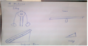
After thinking through how we could implement this task using simple or compound machines we decided on four simple machines. This included a pulley, two inclined planes, a wedge and a lever as can be seen in figure 1.

Figure 1.  Use of four Simple machines in building our own machine

Figure 1. Use of four Simple machines in building our own machine

Subsequently, we put together the four simple machines to come up with a machine we called “Universe.” The concept features an inclined plane that will transport a ball from its place of origin onto a cup like container that is fastened to a lever placed adjacent a pulley. The job of the pulley is to apply a force to the other side of the lever in order to propel the ball into the goal area (box). The universe machine concept can be seen in figure 2.

Figure 2. Sketch of what the whole machine would look like

Figure 2. Sketch of what the whole machine would look like

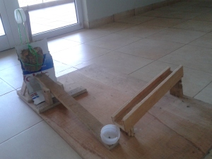
Figure 3. Snapshots of Universe

Figure 3. Snapshots of Universe

Figure 3. Snapshots of Universe

Figure 4. Snapshots of Universe

Implementation

The materials we used to build our machine consisted of plywood board, stone, plastic bottles, paper card and nails. The lever, pulley as well as the wedge were made using the plywood provided. Furthermore, we acquired Tampico bottles from the recycle baskets on campus to enable us create the ball holder. This was not a simple process as many (almost all) of the bins contained only “voltic” water bottles which were too weak to serve as a pulley. The Tampico bottles we found were sawed at the base to obtain the cup-like ball container. Some of the difficulties we faced involved splitting the plywood due to the size of the nails being used on them. Furthermore, it was increasingly difficult to find materials on campus that fit our concept hence we were required to improvise for the plan to be implemented successfully.


Discussion

As already mentioned, building this machine from locally available materials proved to be a challenging. For instance, in building a stand for the pulley we could not figure the height that it should be to give as the perfect projection of the ball placed on the lever. Upon giving it a number of tests we had to change the stand to a much smaller one to get the desired outcome. Also, finding the right stone size and weight to propel the lever proved difficult. However, our machine worked as we desired though we could have adjusted the sizes of our materials for more accuracy in getting the ball into the goal area.


Conclusion

Building our machine proved educative and challenging in that it thought as ways we could reuse waste materials to build useful machines and how that requires creativity and careful thought. It also gave us an amazing foretaste of the robotics course. The experience put our creativity side to the test hence proved interesting. However, our inexperience in carpentry led to time overhead and a longer building process. Nonetheless, we look forward to doing more hands on work in this course.