Maze Task
This task requires us to write software to enable our robot to get through a maze from the specified start location to the goal location. The start location is where the robot starts and the goal location is the brightest part of the maze. The task requires us to use at least two types of sensors to guide your robot through the maze. Our robot should be able to determine when it has reached the goal. When it reaches its goal it should stop on its own and give give some kind of audible indication that it is done.
Idea for navigating maze
After carefully studying the maze, we realised that we could have our robot, “Bumpy”, successfully go through the maze with four main movement strategies. These were: line following, turning right, reverse and going straight. This is not to say that our robot had no need to turn left, but that any where it would have been necessary to turn left, there was a dark trail (or strip) that it could follow.
The line following algorithm we employed work for straight and only curved lines in any direction. This made it possible for us to accurately turn left whenever we really needed to, while sticking to the conventional right turns in the maze since only two out of nine possible turns were left turns.
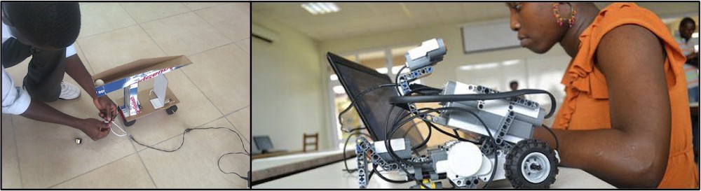
A picture of the maze that got us to appreciate right-hand drive countries
Building the robot to best fit the Maze task
Given the general layout of the maze, the objects to sense within the maze and our little right-hand drive derivation, this is how we decided to rebuild our robot to suit the task.
Sensors used:
Two touch sensors
Only one was connected to a port on the NXT processor. However both touch sensors were connected to a modified bumper we built; to enable the connected touch sensor be triggered even when the unconnected touch sensor was triggered.
Two Light sensor
One for ambient light and the other for for active light
Picture of “Bumpy” the Maze Wizard.
*The sonar sensor in the picture was not used in the Maze Task
Functions available to the Robot:
drive_forward() – to move the robot forward
drive_backward() – to move the robot backward
turn_left() – to turn the robot in the left direction
turn_right() – to turn the robot in the right direction
stop() – to stop the robot from moving
celebrate() – to stop the robot and make a sound after task completion
bumper() – to check if the touch sensors have been triggered, and reverse and turn right if they were
line_track() – to follow the trail of dark lines within the maze
Implementation strategy:
When the robot is started, it first goes straight [using the drive_forward() function] until it either bumps the wall of the maze or it senses the dark trail line. If the robot bumps into the wall of the maze, the bumper() function would be invoked; which will cause the robot to reverse [using the drive_backward() function] and then turn right [using the turn_right() function]. However, if the robot senses the dark trail line instead, the robot would follow the line [by invoking the line_tracking() function]. While tracking the line at any given point in time, if the robot is to bump the wall of the maze, it would again invoke the bumper() function – causing it to reverse and then turn right. Our program iterates this logical sequence with the ambient sensor reading a value greater than 36 as its “operational condition” – the main condition by which the program should run. If the ambient light sensor detects a value less than 36, it stops the robot and plays a sound via the celebrate() function. The celebrate function uses the stop() function to stop the robot motors.
Challenges Faced
Calibration for the different areas within the maze turned to be a little issue as we had difficulty in detecting the light bulb place in the final destination. Anyway, the light bulb blew just before the demo. The final destination was no longer distinguished by the light but rather darkness. This meant we had to re-tweak and re-tweak the program code until we had our calibration and dark-spot logic perfect.
Bumpy bumping into the wall of the maze Bumpy tracking a line in the maze
Wall Following Task
Idea for wall following
We decided to implement bang-bang control for wall following. In order to implement wall following, the robot used three main movement strategies: turning left, turning right and going straight.
The wall following algorithm we used was, to move the robot to the left, if it is less than 6cm away from the wall or move the robot to the right, if it is more than 9cm away from the wall or to move the robot straight, if it is in between 6cm and 9cm.
Functions available to the Robot:
drive_forward() – to move the robot forward
turn_left() – to turn the robot in the left direction
turn_right() – to turn the robot in the right direction
Bumpy trying his hands on the wall Following Task
Challenges Faced
One challenge we faced was where to place the sonar sensor on the robot. If the sonar sensor’s emitter and receiver are not well aligned, the readings from the sensor would be wrong . Also,if the sonar sensor and the robot were not aligned correctly, the reading from the sensor will not be a true representation of the distance of a robot from the wall, especially when the robot is negotiating a bend. We solved both problems by repositioning the sonar sensor very close to the left tyre and aligning it such that its emitter and transmitter were able to send and receive correct values .
Ghana’s problems and solution using sensors
In the northern region of Ghana, lack of electricity is a major problem hence using alternative source of electricity is a solution that has been well discussed by students, government and citizens. Implementing a system that alternates between hydro and solar energy could solve the electricity problem. Having an automated system that switches between the different sources of energy will make the system easy to use and more effective. The sensors that will be used are laser and light sensors. The laser sensors will be use to determine the intensity of a fog if one exists. And the light sensors will be use to read the light intensity. Both sensors will interface to ensure that the light intensity readings are correct. If the light intensity is low due to harmattan or darkness, the power source is switched to hydro energy and if the light intensity is high, the power source is switch to solar energy.
Ashesi University locks its library, labs and lecturer halls at 10pm which prevents students from using these facilities at night. The main reason is, the school cannot keep track of people who use thosefacilities after 10pm. Hence there is no accountability. To solve this problem, Ashesi can implement a system that requires all students, faculty and staff to scan their thumbs before they can enter or exit the library, labs or lecturer hall after 10pm. The sensor the system will use is a thumb scanner.
